Hardware Setup
We utilized a UR7e 6-DOF robotic arm equipped with a pneumatic gripper. Perception was handled by an Intel RealSense D435i RGB-D camera mounted externally to provide a global view of the workspace.
Software Architecture (ROS 2 Humble)
Our codebase is modularized into three primary nodes: Perception, Planning, and Execution.
A. Perception Pipeline (`block_detection.py`)
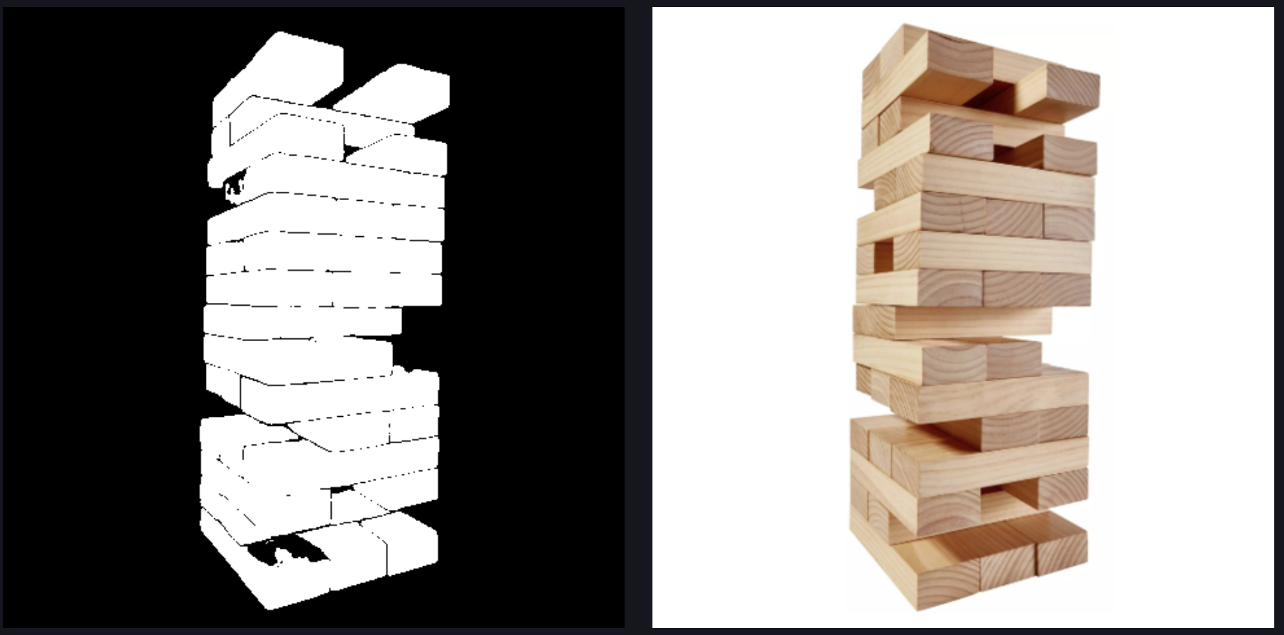
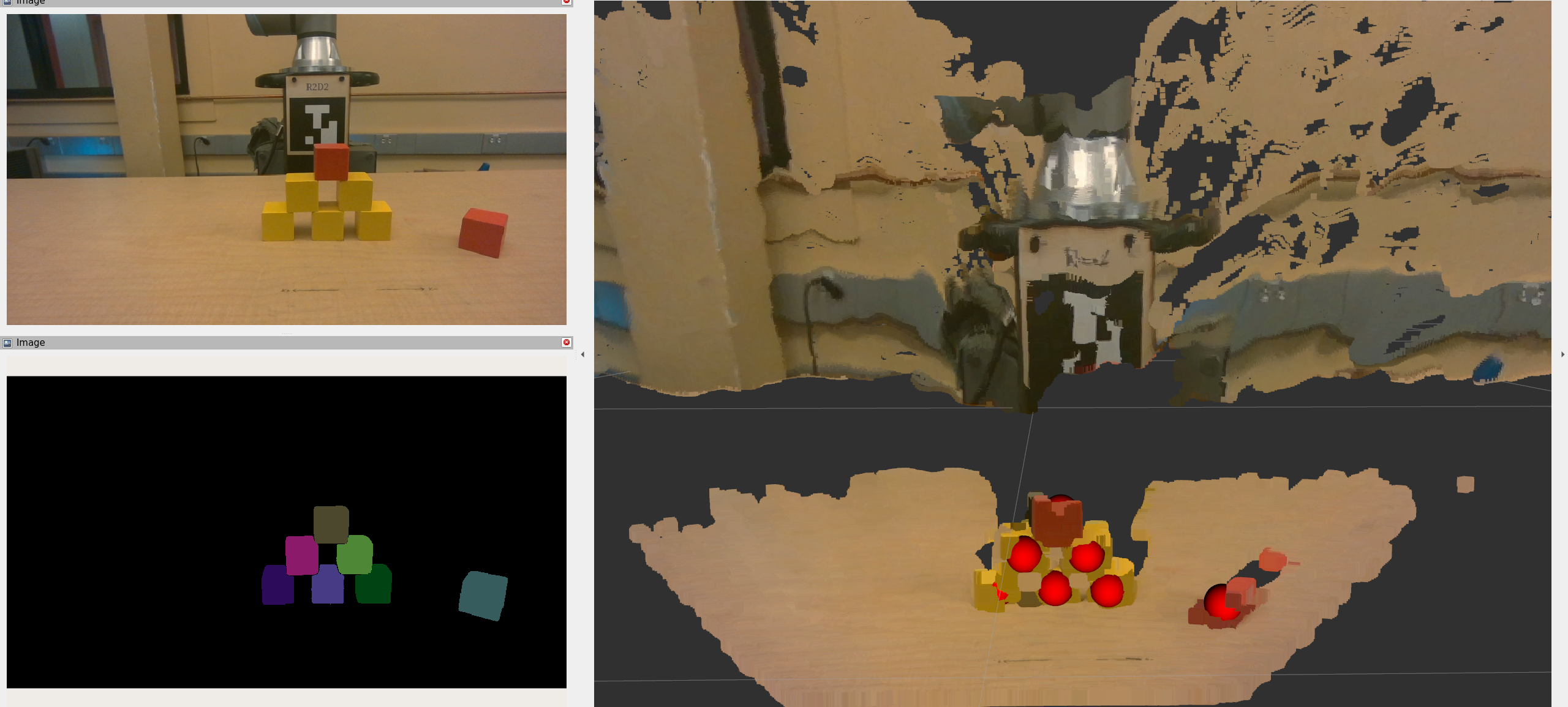
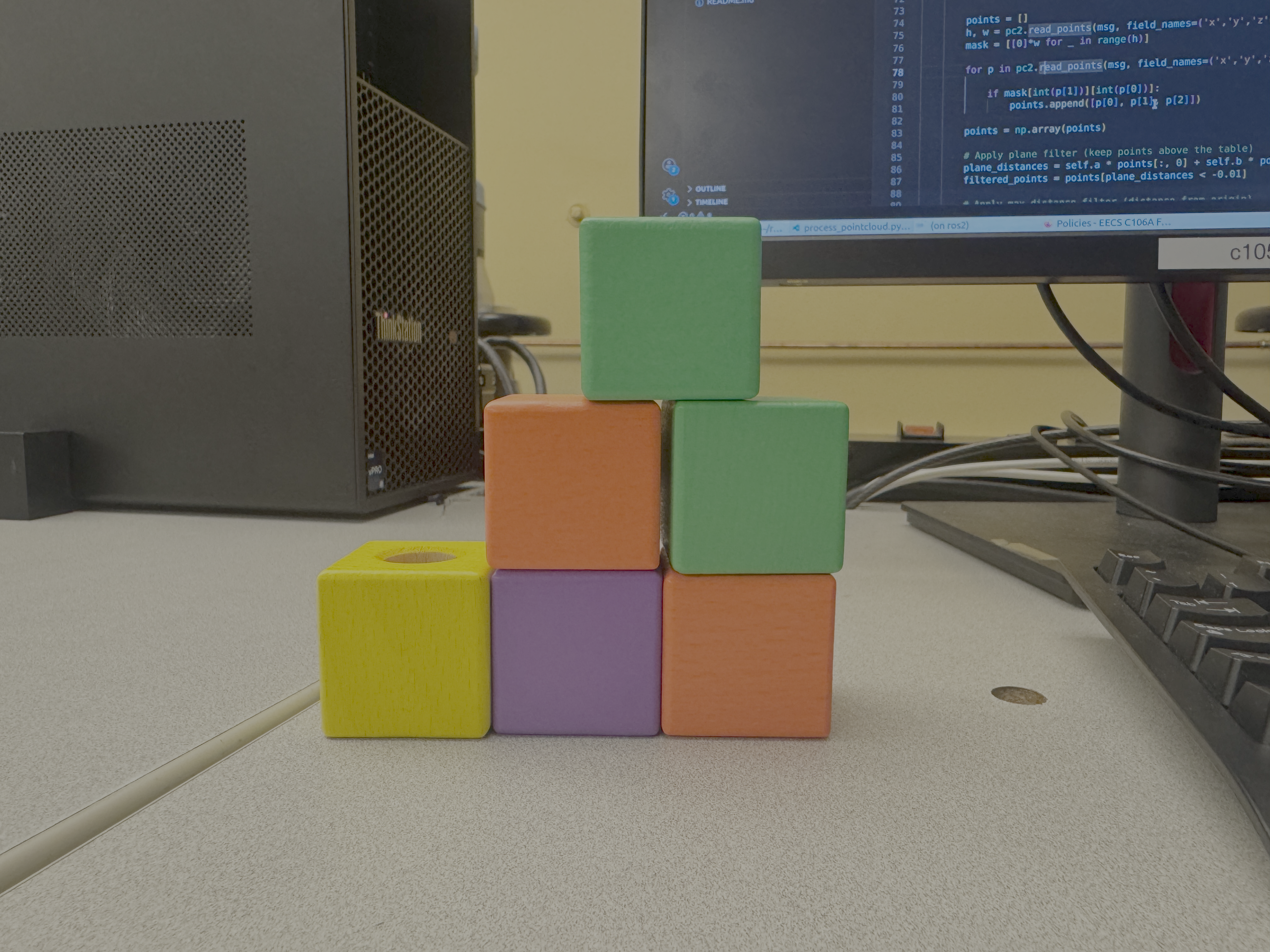
The perception node subscribes to aligned depth and color images. It sends the RGB image to our hosted SAM3 server with the prompt "square cube".
Once binary masks are returned, we compute the 3D centroid of each block. We project the 2D mask centroid \((u, v)\) into 3D space \((X, Y, Z)\) using the pinhole camera model and the depth \(Z\) obtained from the aligned depth map:
$$
X = \frac{(u - c_x) \cdot Z}{f_x}, \quad Y = \frac{(v - c_y) \cdot Z}{f_y}
$$
Where \(f_x, f_y\) are the focal lengths and \(c_x, c_y\) are the optical centers from the camera intrinsic matrix.
B. Coordinate Transformations (`static_tf.py`)
We utilized tf2_ros to manage the transform tree. A crucial step was calibrating the camera frame relative to the robot's base frame. We calculated the homogeneous transform \(G_{base}^{camera}\) such that points detected in the camera frame could be transformed into the robot's planning frame:
point_in_base = do_transform_point(point_in_camera, tf_buffer)
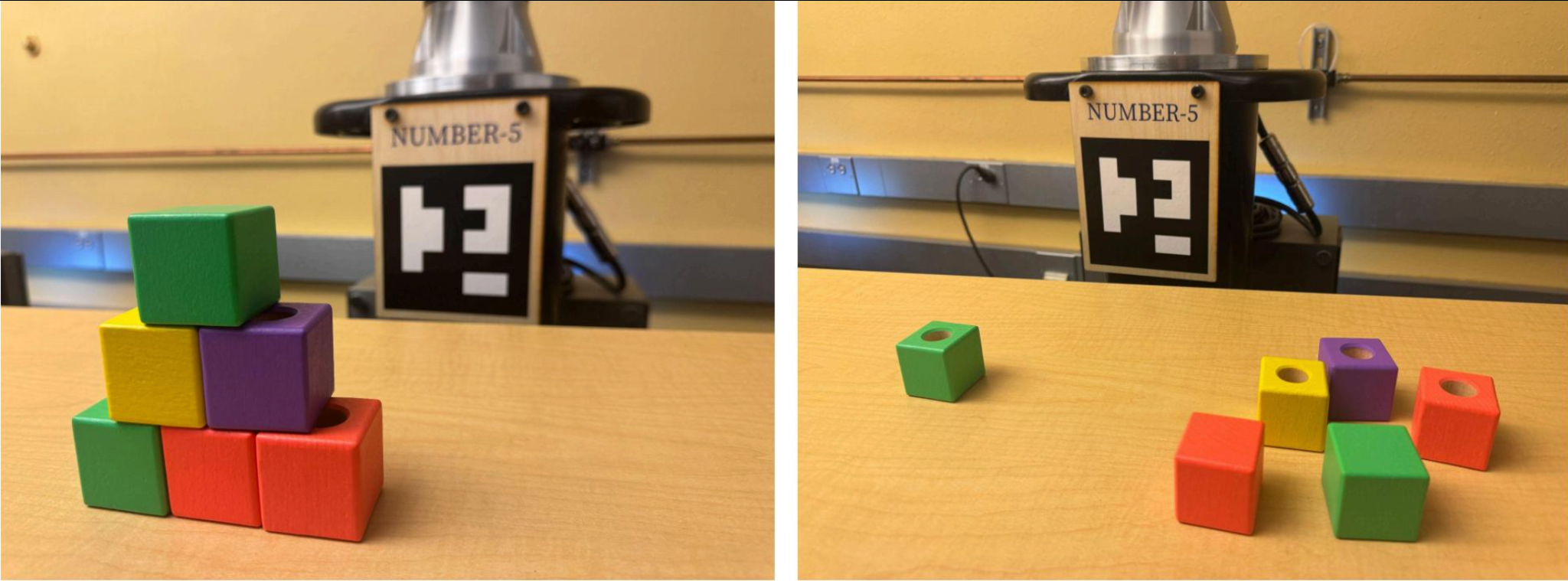
C. Motion Planning & IK (`ik.py` & `disassembly.py`)
We developed a custom Inverse Kinematics (IK) wrapper using the GetPositionIK service. The state machine follows this sequence:
- Pre-Grasp: Solve IK for \(P_{target} + [0, 0, \text{offset}]\) with the gripper orientation fixed downwards (Quaternion: \([0, 1, 0, 0]\)).
- Grasp: Linear descent to \(P_{target}\).
- Retract & Drop: Plan a collision-free path to the bin using MoveIt's
RRTConnect planner.
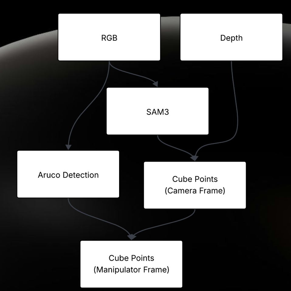 Figure 3: System Data Flow from RGB Input to Motor Execution.